High Temperature Viscometer
Ph.D. Research Project
Design and demonstrate a viscometer for measuring high-temperature liquids as a function of temperature.
Design and demonstrate a viscometer for measuring high-temperature liquids as a function of temperature.
Overview
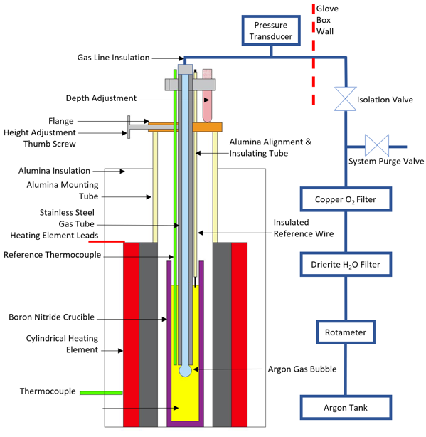
The High Temperature Viscometer is an assembly designed to fit into the
Glove Box Furnace.
Samples are loaded into a slender BN crucible (9mm Inner Diameter, 14mm Outer Diameter, 160mm Length).
It utilizes a Falling Ball Viscometer concept, where a sensor detects a metallic ball after it reaches terminal velocity.
The sensor is used to determine the time it takes for the ball to pass between two set points.
The device is comprised of the following subcomponents:
Ball Drop Mechanism
High Temperature Induction Sensor
Electronic Circuit & Data Collection
High Temperature Induction Sensor
Electronic Circuit & Data Collection
Ball Drop Mechanism
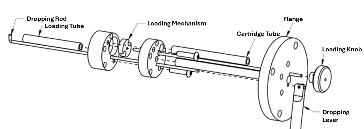
A mechanism for ball-dropping was developed to have a supply of pre-heated balls inside the furnace.
The mechanism allows for balls to be loaded and dropped using controls from the outside of the furnace.
Fabricated with CNC Milling, Turning, Wire EDM property experiments
Assembled using a combination of threaded fasteners and press fitting. Stainless steel alloys of varying thermal expansion were selected to ensure the press-fit was successful at operational temperatures.
Assembled using a combination of threaded fasteners and press fitting. Stainless steel alloys of varying thermal expansion were selected to ensure the press-fit was successful at operational temperatures.
Induction Sensors
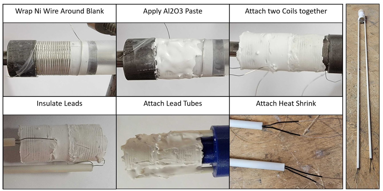
The sensor component is a pair of induction coils designed for high-temperature applications.
The coils are attached to the Electronic Circuit for signal gathering.
Ni wire (30-32 Gauge) wrapped around a blank of the same size as the fluid-containing crucible.
Alumina-Silicon ceramic paste is used to hold the wire shape and electrically insulate the turns from each other.
Alumina rods are used to electrically insulate the leads.
Alumina-Silicon ceramic paste is used to hold the wire shape and electrically insulate the turns from each other.
Alumina rods are used to electrically insulate the leads.
Electronic Circuit & Data Collection
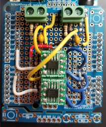
Electronic circuit developed for simple induction measurements directed at determining metallic ball proximity.
Two loops of variation on Tank Circuit with Diode to direct current flow.
Arduino-driven excitation to simulate AC signals for magnetic field generation in Induction Coil.
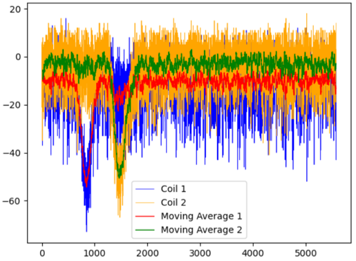
Signals are recorded for post-processing with a low-pass signal filter.
Arduino-driven excitation to simulate AC signals for magnetic field generation in Induction Coil.
Signals are recorded for post-processing with a low-pass signal filter.
Automated Coil Calibration
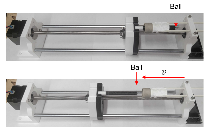
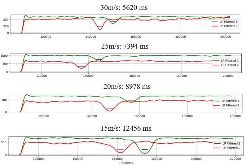
A test fixture for measuring the center-to-center distance of each coil was made using a stepper motor to generate a set velocity for a probe to travel.
The probe was driven through the coils at different velocities, creating signals where the time between each coil center could be determined.
Using the velocity and time, the distance could be calculated.
This distance was used for calculations to determine velocity during high-temperature measurements.
Automated data collection: looped system to collect data.
Stepper motor control system using Arduino as a driver.
Variable velocities demonstrate the ability to measure varying velocities due to changes in viscosity as a function of temperature.
Stepper motor control system using Arduino as a driver.
Variable velocities demonstrate the ability to measure varying velocities due to changes in viscosity as a function of temperature.
Falling Ball Model
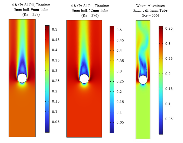
A laminar flow model was built using COMSOL Multiphysics to both design the device through predictive assumptions
for reaching terminal velocity and to help evaluate measurement results.
By creating a correlation for relating velocity across many flow domains, the model avoids complex, unresolvable relationships that would result from purely empirical methods.
The model boundary conditions and features include:
2D Axisymmetric Transient Model
Stationary ball with relative flow driven by gravitational acceleration of the ball
No-slip, translating wall conditions
Viscosity varied to create a lookup table of velocities for densities as a function of temperature
Automated parameter sweeping for lookup table generation
Accurate solvable solutions up to a Reynolds Number of 300, when the solution becomes turbulent

High Temperature Measurement Demonstration
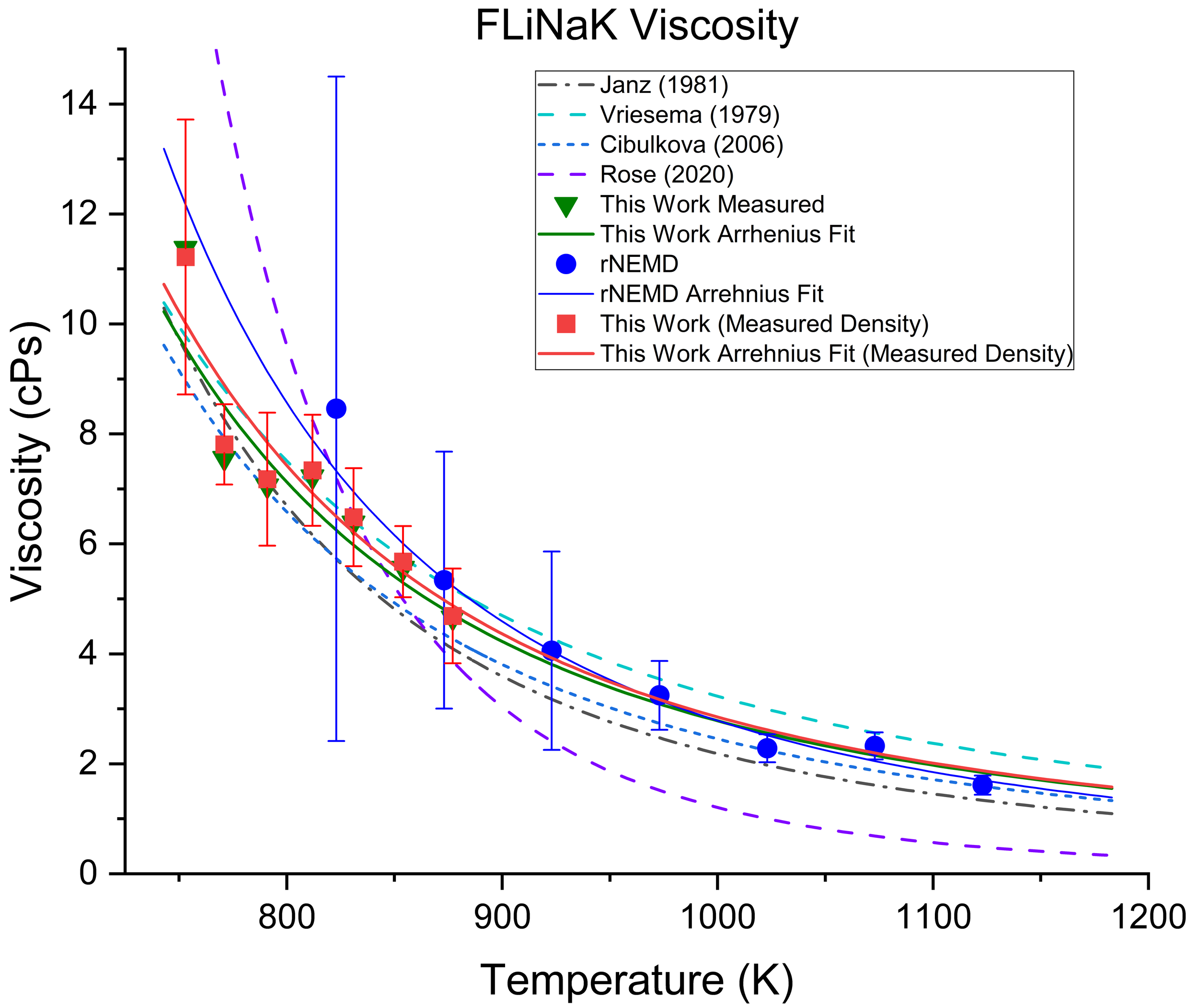
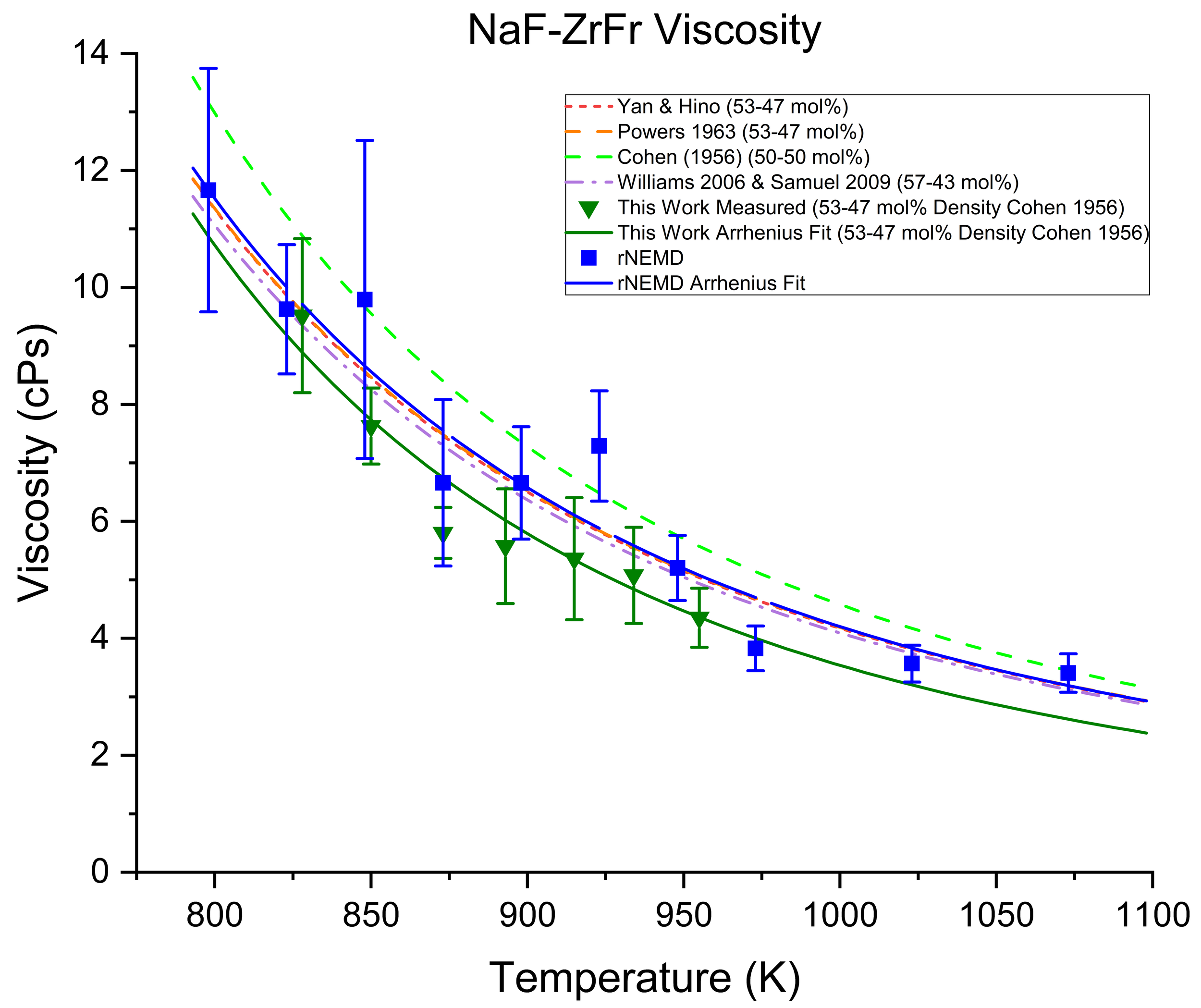
High temperature implantation results in successful measurements of two salts, NaF-ZrF4 (53-47 mol%) and FLiNaK.
-
10% measurement error
Measurements agree with former studies of same or similar salt compositions
